Assigning boundaries to your fluid model
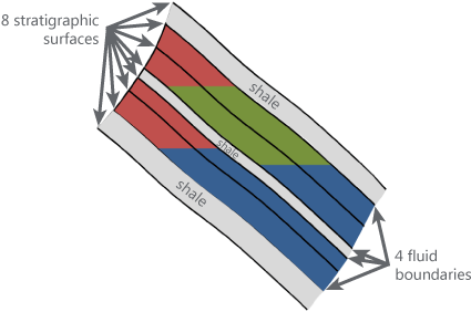
An example of a fluid model illustrating which stratigraphic surfaces to select as the fluid boundary. click to enlarge
With the Assign Boundaries form (model > Fluids > Assign Boundaries) you select which faults and stratigraphic surfaces will form the bounding surfaces of the fluid compartments of your fluid model. Selectable surfaces come from the 'source model' of your choice, i.e. an existing structural model or 3D grid. Make sure to only select those surfaces that are relevant for the fluid compartmentalization. Later in the workflow, after including well data, the initial assumptions regarding compartment boundaries can be revisited in an iterative process.
Consider the following when choosing to base your fluid model on a 3D structural model or 3D grid:
- Extent and resolution of the fluid model compartments - Fluid compartments will adopt their lateral extent and resolution from the selected 'source'. In other words, when you base your fluid model on a structural model, the lateral extent of the fluid model compartments is equal to the lateral extent of the structural model horizons, and the internal resolution will by default be the resolution as defined for the structural model on the model > 3D Structure > Set Modeling Parameters form. This is when the 'Fluid Model Resolution' is set to 'Medium' on the Activate Fluid Zones form, where it can be adjusted to twice as fine or twice as coarse. When you base your fluid model on a 3D grid, the lateral extent of the fluid model compartments will be limited to the lateral extent of the 3D grid and the internal resolution will be the 3D grid cell resolution.
- Difference in performance - When you select a structural model as 'source' for the fluid model, the application creates an internal grid ('under the hood'). When your 'source' is a 3D grid, the application takes a copy of this grid. Most of the time, using a 3D grid as 'source' will be faster, except when your 3D grid has much more cells than the internal grid created from the structural model, in which case copying the existing grid may take longer than creating an internal one.
If your fluid model requires an additional (internal) compartment boundary, you can assign Additional fluid boundaries from the available polyline sets. Note that the selected polyline set should be of the type Boundary and should contain one single polyline. See Using artificial boundaries for an explanation on how additional boundaries can be used.
Once you have assigned the boundaries to the fluid model, the boundaries are available in the JewelExplorer (under Fluid Model > Fluid Boundaries > 'Faults', 'Horizons' and 'Boundaries') and can be visualized in the various views (3D, 2D, Well View).
Note that:
- When your source is a structural model, these faults and horizons are copies from the faults and horizon surfaces in the structural model.
- When your source is a 3D grid, these faults are copies from the faults in the 3D grid, and these horizons are coming from the stratigraphic level assigned to the 3D grid.
To assign boundaries to your fluid model
- At the top of the form, under Model, select the fluid model of interest.
- Under Source type, choose whether to base your fluid model on a 3D structural model or 3D grid and select the model/3D grid from the drop-down below. All the structural models and 3D grids in your solution are available for selection.
- Based on the selected 'source' (i.e. structural model or 3D grid), all faults and stratigraphic surfaces contained in the selection will appear in the tables on the form. Select the faults(s) and stratigraphic surfaces(s) you want to use as fluid compartment boundaries. Also see 'Faults table' and 'Stratigraphic Surfaces table' below for more details.
- Select any additional fluid boundary if needed. This boundary must be a polyline set of type 'Boundary' that contains only a single polyline. See 'Additional Fluid Boundaries table' below and Using artificial boundaries for additional information.
- Click OK to assign the surfaces and proceed to the Activate Fluid Zones form. Otherwise, click Apply to assign the surfaces and keep the Assign Boundaries form open. After the boundaries have been assigned to the fluid model, the Fluid Boundaries folder is created under the active fluid model in the JewelExplorer. Within the Fluid Boundaries item, you can find the faults and surfaces that you assigned to your fluid model.
Fluid boundaries in the JewelExplorer
After the boundaries have been assigned, you can access them in the JewelExplorer under your fluid model (Fluid Models > Your Fluid Model > Fluid Boundaries). You can access the horizons, faults and polyline sets that were used to define the boundaries, and visualize them in the 3D View.
Only the faults that are included in the specified structural model or 3D grid will be available for selection.
Select Check the box for each fault that you want to use as fluid compartment boundary.
Name The names of the faults that are available for selection (read-only).
Length The length of the fault (read-only).
Type The type of the fault (read-only).
Only the surfaces included in the specified structural model or 3D grid will be available for selection. When you select a 3D grid as a Source type, the surfaces listed in the table come from the stratigraphic level assigned to the 3D grid.
Select Check the box for each surface that you want to use as fluid compartment boundary.
Name The names of the surfaces that are available for selection (read-only).
Type The type of the surface (read-only).
Additional Fluid Boundaries table
Use the 'Additional Fluid Boundaries' table to assign a polyline set as a boundary. In order for the polyline set to be used in this manner, the Polyline Set type needs to be set to 'type = Boundary' in the Inspector. The polyline set can contain one or multiple polylines; each polyline will form a separate fluid compartment boundary. For more information about boundaries, see Boundaries and Feature Sets.
Select Check the box for each polyline set that you want to add to the boundary definition.
Name The names of all polyline sets that are available for boundary selection (read-only).
Type The type of polyline set (read-only).